Flywheels
Technical Specification
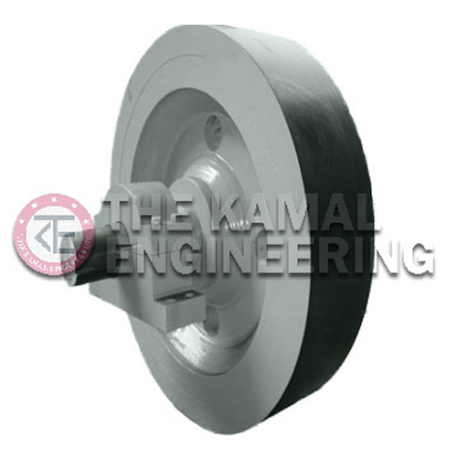
A flywheel is heavy metal wheel attached to a drive shaft, having most of its weight concentrated at the circumference. Main function of flywheel is to reduce speed fluctuation by storing extra energy during part load as kinetic energy and same is released during overloading. By slowly increasing the speed of a flywheel a small motor can store up energy which enables the motor to perform a function for which it is ordinarily too small. Shaft calculations incorporate a high safety factor and are validated by bending and torsion stress analyses.
We at “THE KAMAL ENGINEERING” provide Flywheels as per the following configuration.
| WEIGHT | Maximum up to 30 M.T. Approx |
| TYPE | Rim Type |
| MATERIAL | Cast Steel & Graded Cast Iron |
| BALANCING | Statically & Dynamically Balanced |
| SHAFT MATERIAL | Forged EN – 8 or 9, Class IV Grade |
| SHAFT SUPPORT MECHANISM | Fabricated Pedestals with Bearing Blocks & Heavy Duty Spherical |
| ROLLER BEARING RINGS | Shrink fitted into shaft for retention of flywheel |
| PEDESTAL | Steel fabricated for bearing block support |
| MAX. SPEED | 50 RPM to 1000 RPM |
Other technical & design details about the Flywheel such as GD2, Inertia, Torque, Bearing No., Outer Dia. & Rim thickness etc. can be provided on request by the buyer.
Designing & Construction Process of Flywheel: –
- Fully machined & bored on VTL up to Zero oddness
- Statically, Dynamically & Mechanically Balanced
- Ultrasonically Tested (As per Requirement)
- All Sizes within the Blasting Range of the Material
- Flywheel is designed taking into account maximum possible energy
fluctuation Encountered in service